
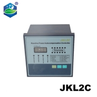

JKL2C with power supply 220v 12 steps Reactive power factor compensation controller 50/60Hz for switchgear
93.31 $


1. INTRODUCTION
PFR Series reactive power auto compensating controller is suitable for self-adjusting capacitor compensating devices in low voltage distribution system (hereinafter referred to as controller) and make power factor reach the presetting state by user to increase the utilization efficiency of power transformer, reduce line loss and improve voltage quality, thereby to increase the economic and social benefits.
2. FUNCTION CHARACTERISTICS
1.To calculate the input-cut capacitance by reactive power,with high precision compensation.
2.Power factor has high precision measurement, with wide displaying range.
3.Initial phase preset(homonymy terminal of software adjustment or current polarity).
4. With friendly human-machine interface, easy to operate.
5. All kinds of control parameters can be adjusted in whole digit. It is visual and easy to use.
6. With two working modes: auto run and manual run.
7. With protection function of over voltage and under voltage,
8. With power down protection function, so data will not lose.
9. With low current signal input impedance ≤0.01Ω.
3. SERVICE CONDITIONS
1. Altitude does not exceed 2500m.
2. Ambient environment:-25℃~+50℃.
3. Relative humidity:<50% at 40℃ and<90% at
20℃.
4. There is no corrosive gas,conductive
dust,combustivle explosive medium around.
5. No severe vibration in installation place.
4.DEBUGGING
Warning:During the process of adjustment,user should abide by the following adjustment
steps. The one with (*) is the controller working under reactive power control mode.
a. Assemble the compensating device according to the demand of connection diagram, and then make adetailed examination so as to remove the mistake that may cause serious potential safety hazard.
b. Switching in compensating device,the controller enters into automatic state.
*c. Input the transformation ratio ofat site signal current transformer, for the details see Parameter Preset.
*d. Input the capacity of capacitor of each branch circuit, for the details see Parameter Preset.
e. Operate "MENU" key to make indicator light of manual run shines. As one measure for debugging compensating device, manual run can be sued for checking its connection correet or not. Operate
"▲" key, one capacitor group input,and operate "▼" key, one capacitor group cut.
Note:The output terminal,the capacitor value of which is zero,can't perform input and cut action.The above operation can be without current signal.
f. In order to make the controller automatically input and cut capacitor group,besides user should put menu under menu of "Power factor" or "eactive power", the current signal should lag voltage signal, and the system voltage is not higher than over voltage protective value and is not lower than under voltage protective value.
5.KEY FUNCTION
Menu key “MENU”: Main menu and submenu for option. Note: Press menu key for 3s to enter into parameter preset menu.
Increase key“▲“: Preset parameter to increase the data, input capacitor group when for manual run.
Decrease key“▼“: Preset parameter to decrease the data, cut capacitor group when for manual run.
Under menu"Power factor" display primary current A.Under menu"Reactive power" display voltage signal V.
6.Parameter preset

Note:
①When signa voltage signal and current signal input to the controller are on Positive polarity,user
should adjust the parameter to"0"; When they are on Reverse polarity,user should adjust the parameter to"180"; If user can't judge polarity, off all load, then input one group or several groups capacitors,now the power factor that controller displayed is ncgativeand very low.If the power factor is not negative,it can be judged that the voltage signal and current signal are on Reverse polarity.If the initial phase is"180",user should adjust it to"0"and while itis"0",user should adjust it to"180", User should confirm this parameter correct or not after one controller is finished installation,or will cause the abnormal operation for controller.
②CT transformation ratio preset value is the numerator value of signal current transformer ratio.Eg.User's signal current transformer ratio is 500/5A,then the CT ratio preset value is 500,not is 100.
③The output loop capacitance should be preset to"O" if without connected with capacitor.
The output loop controller will not oulput control signal if the preset capacitance of capacitor is"0",
7.Input-cut principle
1) When the capacitor bank can't input automatically, user should consider the following condition
is tenable or not.It should be noted that the following conditions are necessary,must fulfil.
a.Power factor value of system is lower than target power factor value.
b.Over voltage indicator light doesn't light.
c.We indicate active power of present electric network by P and reactive power by Q.target power factor by cosφ.Formula l must be tenable.

2) When the power factor of electric nerwork is higher than target power factor, and the capacitor bank can't cut automatically, user should consider the following conditions is tenable or not.Use P to indicate the acuive power of electric network, Q to indicate reactive power of present electricc network and cosφ to indicate target power lactorl.Formula 2 must be tenable.

8.Display instruction
Over voltage: If the present menu indicator light flashes frequently, which means the controller works on overvolt thedisplay value is system voltage value
Cosφ value: Displaying 0.985 means present power factor is lagging 0.985.
Displaying-0.985 means present power facor is leading 0.985.
Under current: Displaying “CO” means undercurrent, signal current is less than 50mA
9. CONNECTION DIAGRAM
Operating Voltage(Un):......380V
Operating Frequency:........50/60Hz
Operating Power:...............<12VA
Operating temperature:.....-20;℃ to 50℃
Current Measuring Range:..0.5mA-5A
Measuring Accuracy:...........%±1%
Current Transformer Ratio:....5/5A-9999/5A
Response Time:...............0.4sec. - 250sec.
discharge Time:...............0.4sec. - 250sec
Number of Steps:.............6 Steps;12 Steps
Connection Type:.......Plug-in terminal connection
Contact:........................3A/250VAC Resistive Load
Weight:..........................<850gr.
Panel Hole Sizes:..........140mm x 140mm
Protection class:...........IP40
Operating Altitude:........<2000 meter
10.Connection Diagram

Perforate dimension:144*144mm
1、3 Voltage signal input terminal
5、6 Incurrent signal input terminal
23 Common terminal of control output terminal

We are proud to offer international shipping services that currently operate in over 200 countries and islands world wide. Nothing means more to us than bringing our customers great value and service. We will continue to grow to meet the needs of all our customers, delivering a service beyond all expectation anywhere in the world.
Packages from our warehouse in China will be shipped by ePacket or EMS depending on the weight and size of the product. Packages shipped from our US warehouse are shipped through USPS.
Yes. We provide free shipping to over 200 countries around the world. However, there are some location we are unable to ship to. If you happen to be located in one of those countries we will contact you.
We are not responsible for any custom fees once the items have shipped. By purchasing our products, you consent that one or more packages may be shipped to you and may get custom fees when they arrive to your country.
Shipping time varies by location. These are our estimates:
| Location | *Estimated Shipping Time |
|---|---|
| United States | 10-30 Business days |
| Canada, Europe | 10-30 Business days |
| Australia, New Zealand | 10-30 Business days |
| Central & South America | 15-30 Business days |
Yes, you will receive an email once your order ships that contains your tracking information.
For some shipping companies, it takes 2-5 business days for the tracking information to update on the system.
For logistical reasons, items in the same purchase will sometimes be sent in separate packages, even if you've specified combined shipping.
If you have any other questions, please contact us and we will do our best to help you out.
All orders can be cancelled until they are shipped. If your order has been paid and you need to make a change or cancel an order, you must contact us within 12 hours. Once the packaging and shipping process has started, it can no longer be cancelled.
Your satisfaction is our #1 priority. Therefore, if you’d like a refund you can request one no matter the reason.
If you did not receive the product within the guaranteed time(45 days not including 2-5 day processing) you can request a refund or a reshipment.
If you received the wrong item you can request a refund or a reshipment.
If you do not want the product you’ve receive you may request a refund but you must return the item at your expense and the item must be unused.
*You can submit refund requests within 15 days after the guaranteed period for delivery (45 days) has expired. You can do it by sending a message on Contact Us page
If you are approved for a refund, then your refund will be processed, and a credit will automatically be applied to your credit card or original method of payment, within 14 days.
If for any reason you would like to exchange your product, perhaps for a different size in clothing. You must contact us first and we will guide you through the steps.
Please do not send your purchase back to us unless we authorise you to do so.

Thank you for your interest doing business with us!
If you would like to get a discounted price for your large purchase orders, fill in the required blanks along with your email address, the product Item ID # and/or the link of the item that you want to order, item quantity (minimum of 30 pieces), shipping country and payment method is required. We will contact you with a discounted price as soon as we receive your inquiry.
HOGAKI.com
member of COOCOP LLC.
30 N Gould St, Ste R
Sheridan, WY 82801
United States
Registration with your email to receive more information about products, on sale, promotion, services and offers.
© 2017-2023 HOGAKI.COM - Home, Garden & Kitchen shop.